Ensure the pointer aligns with zero when no current flows. Adjust using the Zero Adjuster screw if necessary.
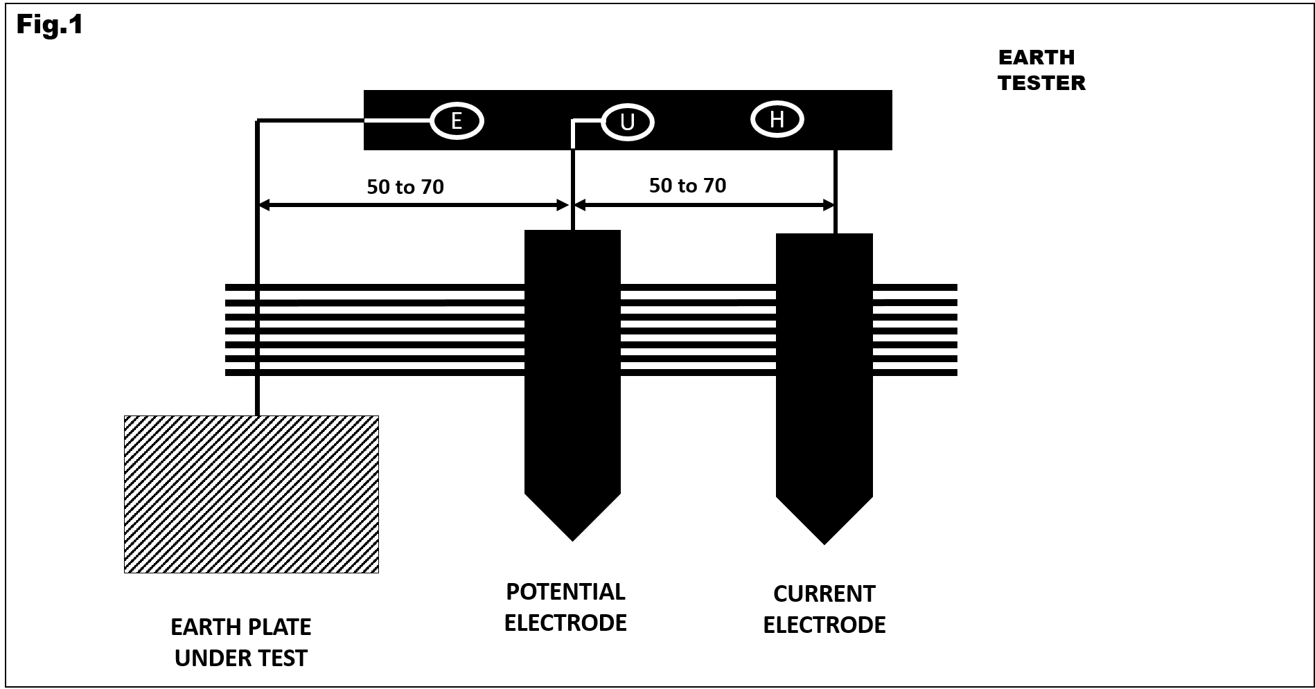
Attach all three terminals as per Fig. 1. Rotate the generator handle until the pointer stabilizes to read Earth Resistance.
For multi-range instruments, begin with the highest range and adjust downward to ensure accurate measurements.
This tester includes terminals C1, P1, P2, and C2. It is suitable for Earth Resistance and Soil Resistivity measurements.
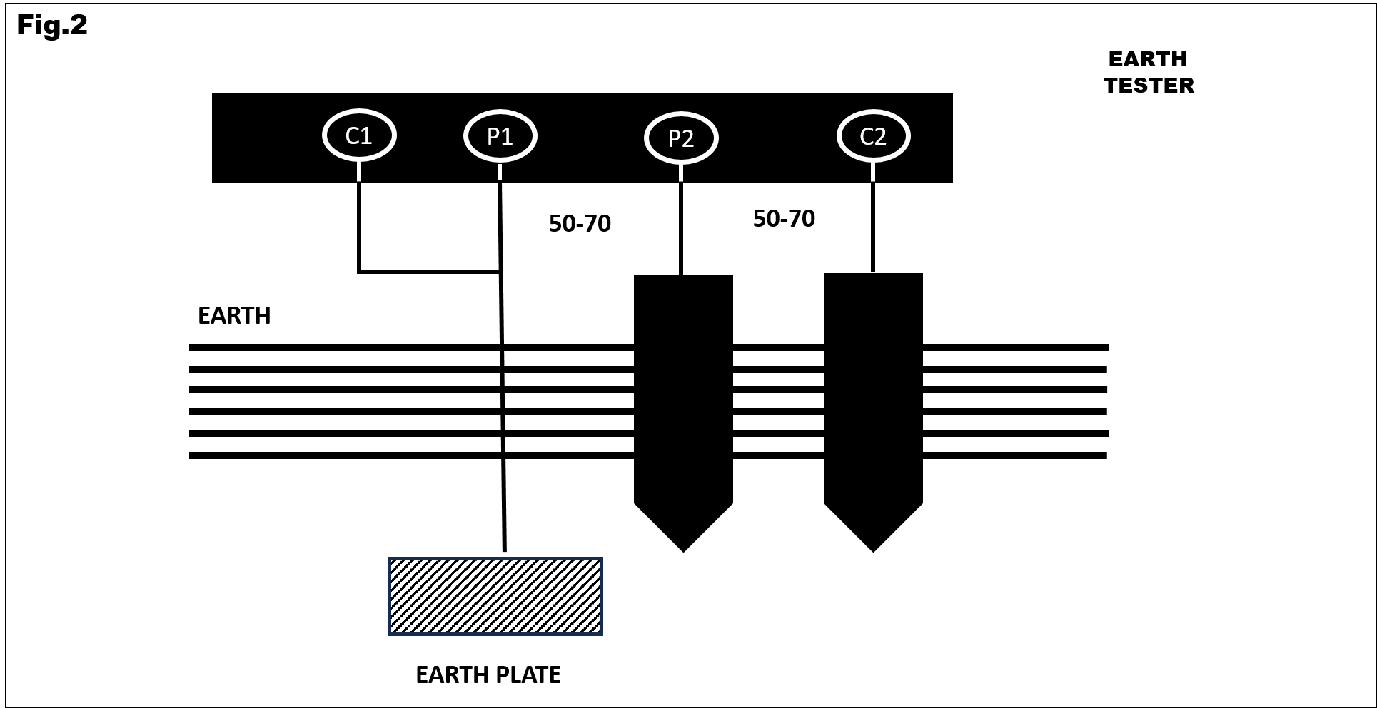
Connect terminals C1 & P1 as per Fig. 2. Rotate the generator handle until the pointer stabilizes, then read the resistance.
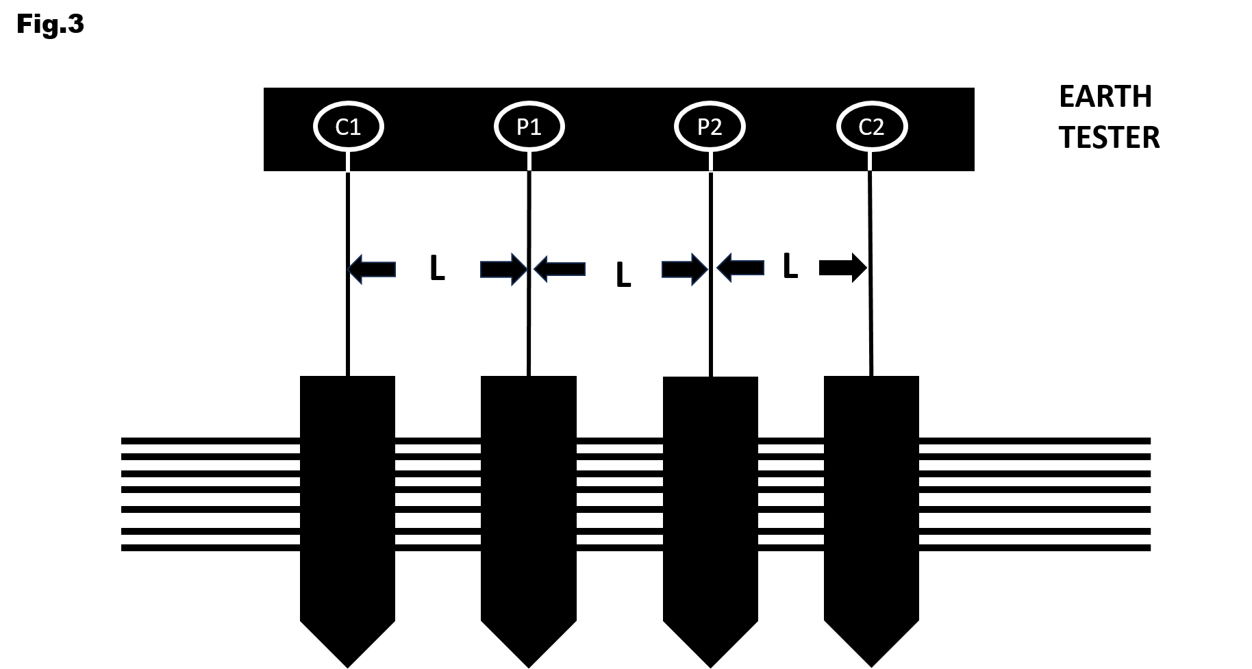
Place four spikes in a straight line, keeping equal spacing (50-70 feet) as shown in Fig. 3, and connect the tester.
BY means Four Terminal type Earth Tester ( use as Three Terminal Type) In Four Terminals type, short the terminals C1 & P1 and connect as per Fig.NO.2. Rotate the handle of generator until the pointer comes to rest. Read the earth resistance directly in ohms.
This is made usually by using Four Terminal EARTH TESTER. Connect the instrument terminals as per Fig.No.3, see that all Four Spikes are one straight line and the distance between all the spikes are kept same. The value of ‘L’ as in Fig.3, may be kept between 50 to 70 feet.
Rotate the generator handle speedily until the pointer comes to rest. Observer the reading of the instrument in ohms (taking care of the range factor). The value of Earth Resistivity o = 2πRL where,
Ensure the pointer aligns with zero when no current flows. Adjust using the Zero Adjuster screw if necessary.
Attach all three terminals as per Fig. 1. Rotate the generator handle until the pointer stabilizes to read Earth Resistance.
For multi-range instruments, begin with the highest range and adjust downward to ensure accurate measurements.
This tester includes terminals C1, P1, P2, and C2. It is suitable for Earth Resistance and Soil Resistivity measurements.
Connect terminals C1 & P1 as per Fig. 2. Rotate the generator handle until the pointer stabilizes, then read the resistance.
Place four spikes in a straight line, keeping equal spacing (50-70 feet) as shown in Fig. 3, and connect the tester.
BY means Four Terminal type Earth Tester ( use as Three Terminal Type) In Four Terminals type, short the terminals C1 & P1 and connect as per Fig.NO.2. Rotate the handle of generator until the pointer comes to rest. Read the earth resistance directly in ohms.
This is made usually by using Four Terminal EARTH TESTER. Connect the instrument terminals as per Fig.No.3, see that all Four Spikes are one straight line and the distance between all the spikes are kept same. The value of ‘L’ as in Fig.3, may be kept between 50 to 70 feet.
Rotate the generator handle speedily until the pointer comes to rest. Observer the reading of the instrument in ohms (taking care of the range factor). The value of Earth Resistivity o = 2πRL where,